Ball Turner Build: 1
Intro and milling the tee slot base
This is a companion article to the original post detailing the construction process.
- Introducing Jim’s ball turner
- The build, part 1: tee slot base [this post]
- The build, part 2: swivel puck assembly: lathe work
3D model and CAD drawings
As I wrote previously, I’ve made a 3D model available for viewing and download as well as a set of dimensioned drawings for my lathe.
For anyone using modeling software other than Fusion360, here are the step files for the design.
The dimensions are for my lathe specifically, but the model is fully parametric (if you use Fusion360). You can just enter the dimensions for your lathe, etc., and the model should update automatically (Modify -> Change Parameters). Just let me know if I’ve screwed something up.
My blog very intentionally doesn’t support comments or questions, but if you’d like to discuss this further, please see this thread on the Hobby Machinist forum.
Introduction
Jim’s ball turner is a great beginner project for anyone with a lathe (and hopefully a mill of some sort). The design is easy to make and quite forgiving, but it demonstrates many aspects of machining. Best of all, if you make it, you’ll end up with a useful tool.
What follows is a long, absurdly detailed description of how I went about making the parts. There are lots of ways to do things, but this post describes how I went about it.
This is a very simple and incredibly tolerant design, though. Don’t let all this drivel scare you off.
There is absolutely no need to try to hit every dimension to 0.0001”. It’s absolutely possible to make this with nothing much more than a lathe. I have a lot of tools, so I tend to use them. With care, all you really need to build this is a lathe and some basic tools.
I describe things at this level of detail to help beginners. I’m not much more than a beginner myself, but I’ve picked up things over the years that I wish I’d understood better when I was starting.
The base
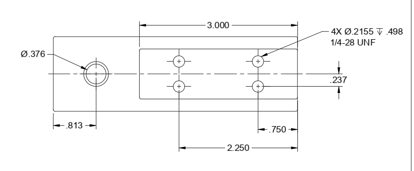
Let’s start by milling the tee slot base. This is a pretty straightforward part to make: just milling, drilling, reaming, and tapping. None of the dimensions are critical except for the diameter of the reamed hole in the end for the puck.
The dimensions in the drawings are for my lathe, though — it’s quite likely that your lathe will differ.
Tools I used
- Horizontal bandsaw (a hacksaw works fine but is harder work!)
- Vertical mill with DRO (dials and indicators also work if you don’t have a DRO)
- 3/4” roughing end mill (any end mill will work)
- Mill vise
- Parallels to raise up the work
- Jacobs chuck with R8 adapter to fit my spindle
- Edge finder
- Dial indicator and mag base (to tram and orient the vise)
- 142 deg “spotting” drill (the tip of a center drill also works)
- #3 drill (tap size for 1/4-28 @80% thread engagement). A 7/32” or 5.5mm drill also works.
- 1/4-28 taper or plug tap
- Letter U drill or 23/64 drill (pre-drill for the reamed hole)
- 0.3760” chucking reamer
- Single flute chamfering tool
- Scotchbrite wheel on a 6” buffer to deburr all edges (a file, carbide scraper, or Dremel tool will work just as well)
That’s a long but pretty complete list. You don’t need all of these tools to make such a simple part, but these are what I used in the process.
Preparation
Ensure the mill head is trammed such that the spindle is perfectly perpendicular to the table, and the fixed jaw of the vise is indicated parallel to the X axis.
Bandsaw the rough stock from a length of 1/2” thick cold rolled steel to rough size (cut out the rough stock slightly oversize in length and width, maybe 1/8” in each direction).
Pretty much any metal you have on hand will work, but steel is better than something soft like aluminum.
Mill the bar to width and length
Stand the part up on edge in the vise, then mill the edge on top with the end of your cutter until it is cleans up and is perfectly parallel to the table (i.e. flat). Then flip the part over and mill the other side until the part is exactly 1.415” wide.

You can minimize the burr that forms if you climb mill rather than conventionally mill. Climb milling means moving the table toward the left when the cutter is over the back half of the exposed edge (traversing the cutter right), and traversing left when it’s on the front edge. Only do this if you take relatively light cuts and know the gibs on your mill are reasonably tight (the cutting forces can pull the cutter into the work).
Note that I didn’t bother milling the wide faces. Since the wide unfinished faces don’t bear against anything, there is no point in machining them.
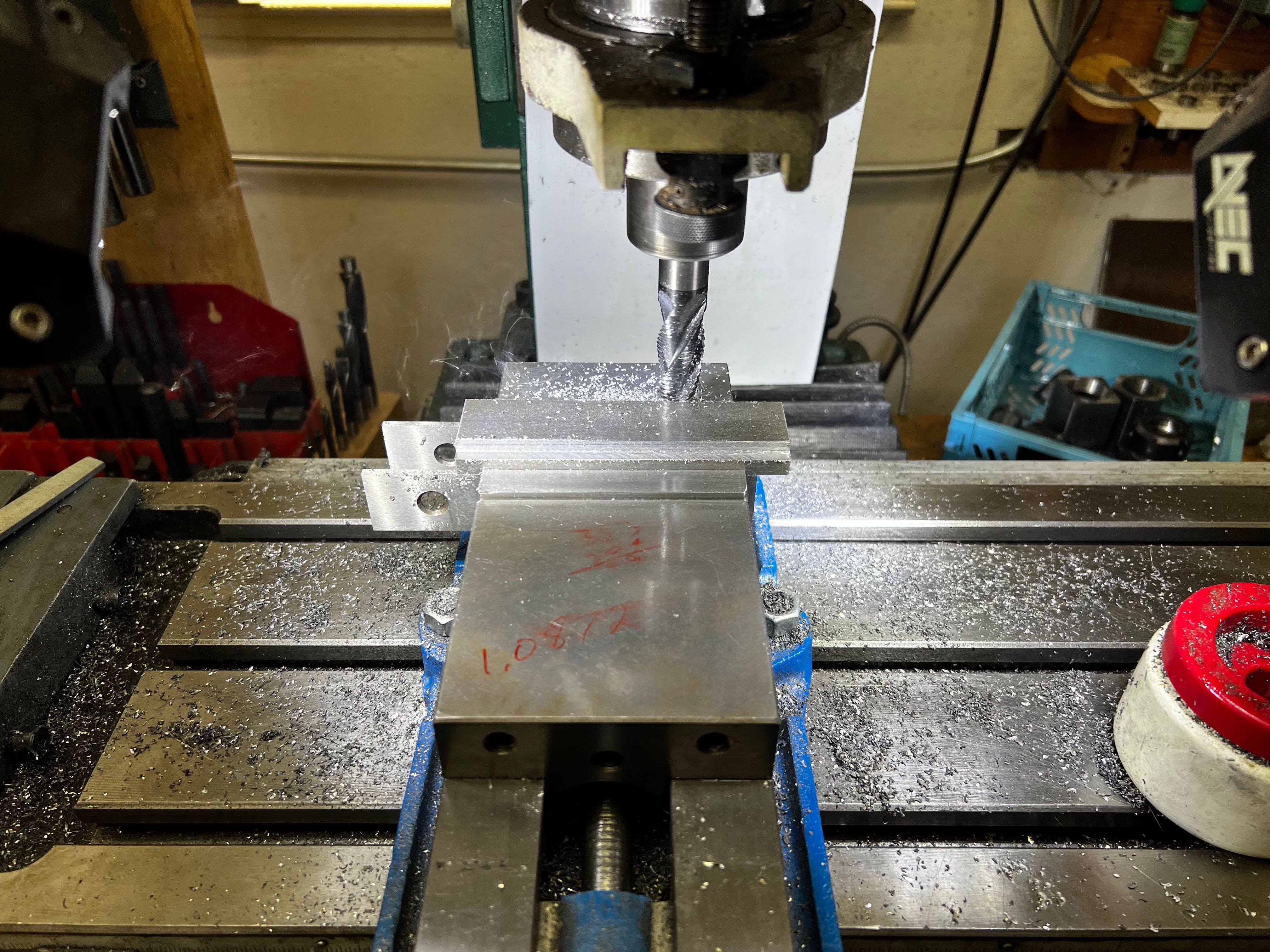
Next, put the part on parallels in the vise as shown in the photo above (tapping it down with a hammer until the parallels don’t move ensures it’s fully seated).
My small 4” vise left enough of the part exposed to mill both ends and the ledge feature all the way around.
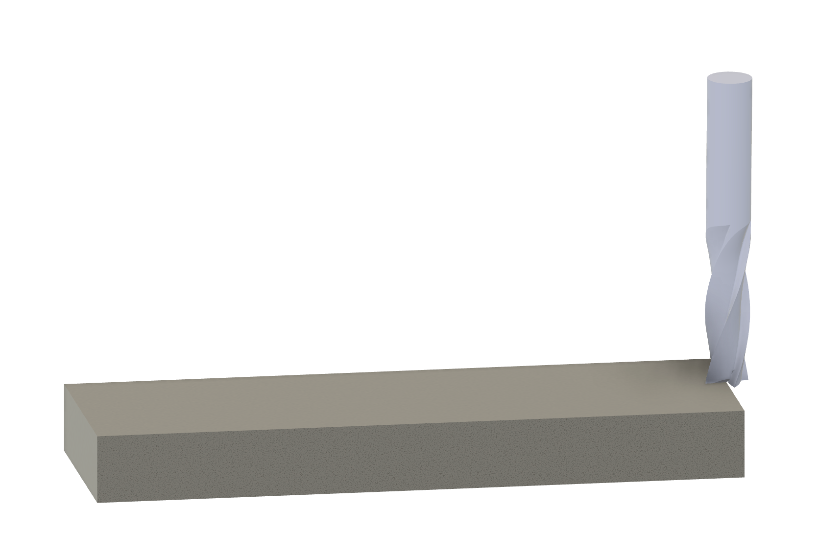
Now move the cutter to the right edge, lower the cutter, and mill along the entire right edge with the side of the cutter. Continue until the entire face cleans up (move the table right each pass until the face on the end fully cleans up).

Don’t touch the cranks at this point and zero the X axis on the DRO. Now raise the spindle, and move the table left by half the diameter of the cutter (0.375” in my case). Re-zero the X axis on the DRO (the spindle is now directly over the right edge).

This makes your absolute zero reference the right edge of the part. If X reads 0.0000 in absolute mode, you know the axis of the spindle is directly over the right edge. Always know what you are using as a reference feature!
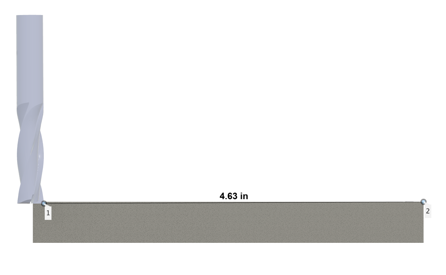
Since we want the part to be exactly 4.635” long, move the table to the right until the DRO reads -4.6350 on the X axis (with the center of the spindle over the left end of the part). Now switch the DRO to “incremental” mode and re-zero X.
The absolute mode “X=0” point is still over the other end of the bar, we re-zeroed in incremental mode which is a separate, second coordinate space. Right now, “X=0” in incremental space means the spindle is over the left edge oof the part.
Now move the table right half the cutter diameter again (.375) and re-zero yet again. Now the right edge of the cutter is exactly over where the bar should end and the DRO (in incremental mode) reads “X=0”.
Move the cutter further left until it’s off the bar. Now mill away material on the the rough cut left end of the bar. Continue milling away material on the end until the DRO reads X=0.0000.
At this point, the rough stock is milled to the exact length and width required. The next step is to mill the ledges and platform for the puck.
Locate the middle
First we must locate the middle of the bar with an edge finder:
Move the edge finder to the front and retract the table until it jumps.
Go back to absolute mode and zero the Y axis on the DRO.
Reposition the edge finder to the back, then feed in the table until it jumps again. Use the 1/2 function on the DRO (or just feed in in Y until it reads half the displayed value, then re-zero).
Now X=0.0000 / Y=0.0000 in absolute mode indicates when the spindle is exactly over the right edge and in the middle of the bar.
Mill the ledges and platform
Let’s mill the front ledge first. Feed in in Y until the DRO reads 0.7500 (the diameter of my cutter). At this point, the edge of the cutter is over the center of the bar.
Switch back to incremental mode, and zero Y. We want X=0.0000/Y=0.0000 to be our absolute reference for all further movements, so we only use incremental mode for temporary, in the moment, relative motions.
The “upper deck” of the tee is 0.949” wide. Half of that is 0.4745, so feed in until the DRO reads Y=0.4745. Lock the table and mill away the front edge to a depth of 0.194”.
Now unlock the table and retract until the DRO reads Y=-0.4745. Lock the table again and mill away the back edge.
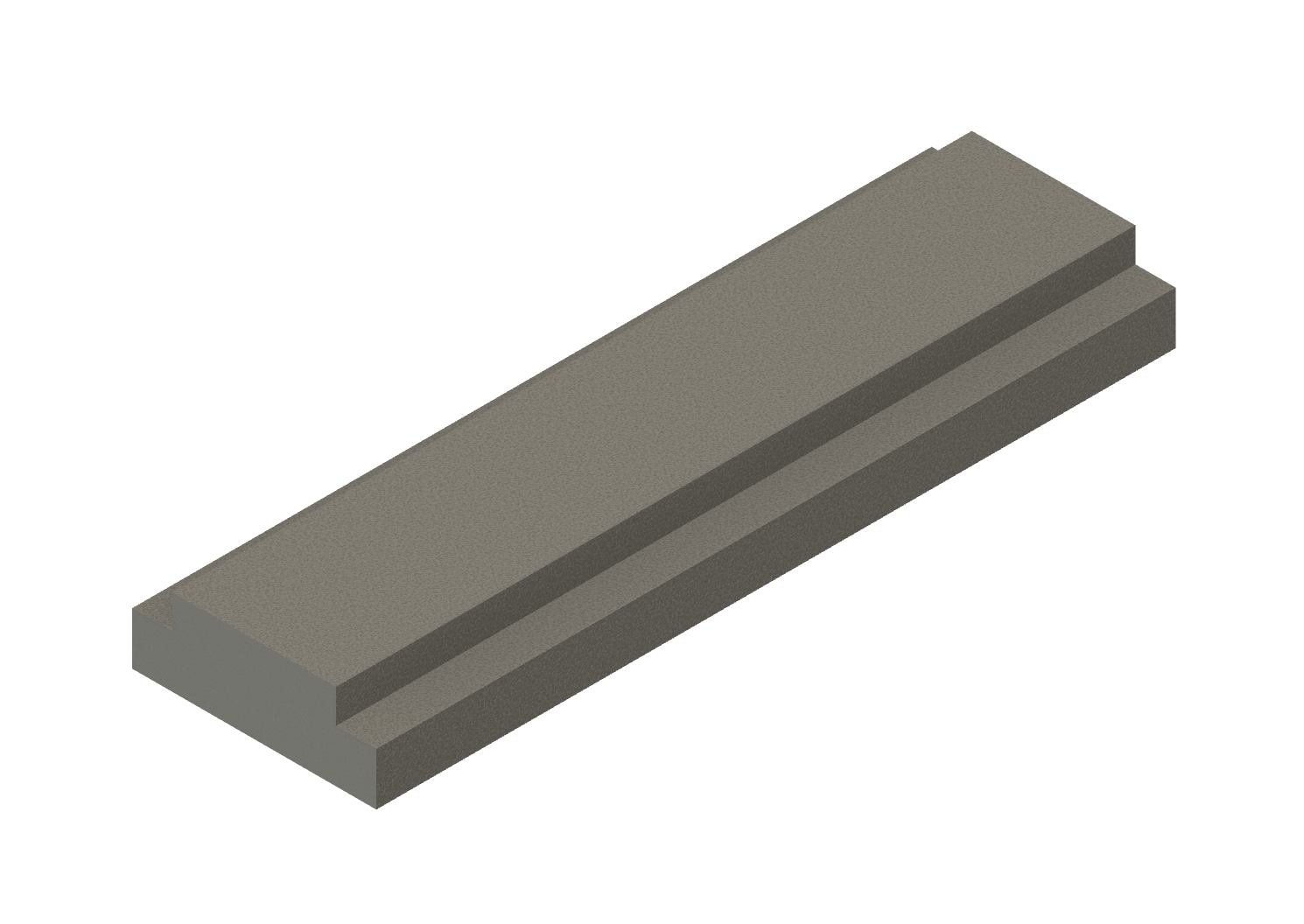
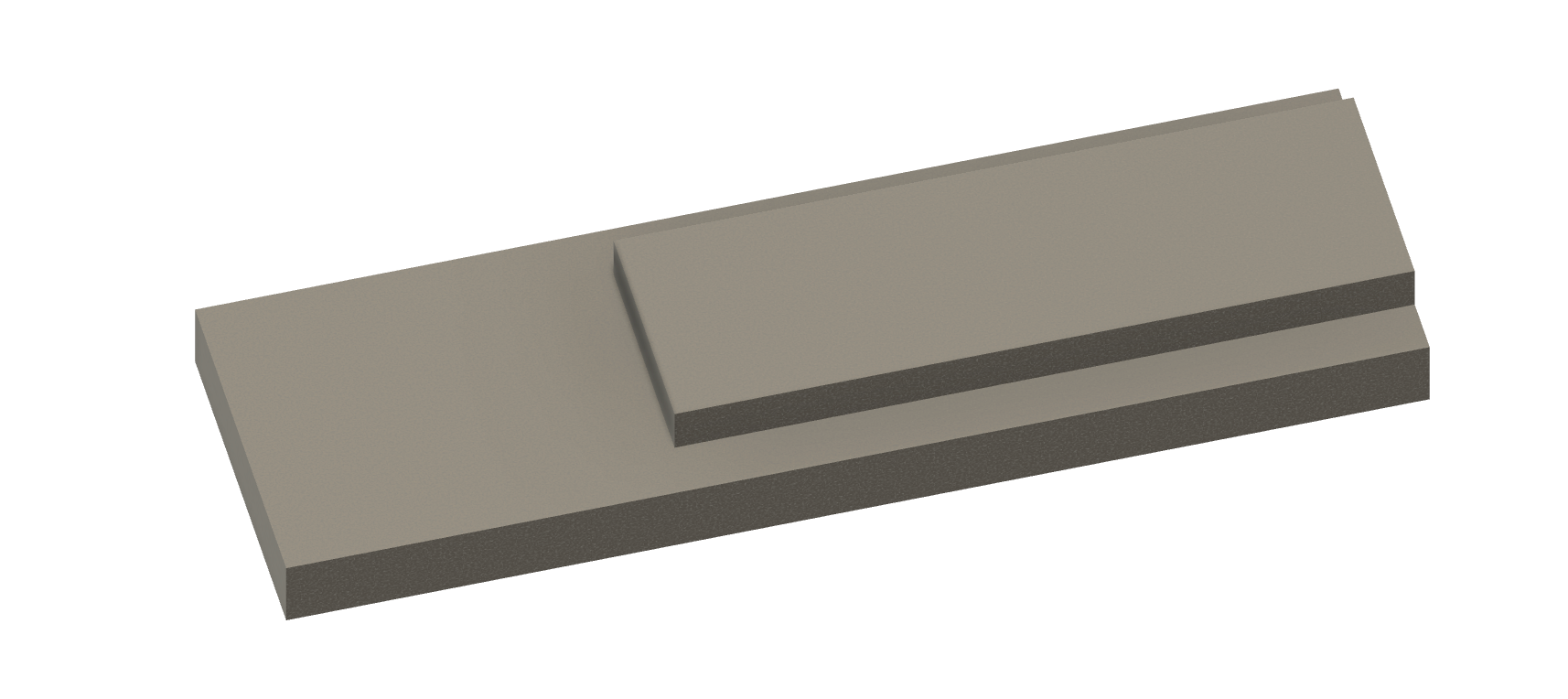
Now we want to mill away the “platform” on the left.
Go back to absolute mode momentarily.
We want the right edge of the cutter 3.0000” from the right edge, so move the table right until it reads -3.3750” (3” plus half the cutter diameter). Back to incremental, and zero X. Now mill away the raised section the left of that point.
Before drilling and tappping any holes, you’ll want to test the fit in your compound, making adjustments if necessary.
One thing that trips up many beginners (and experts) is removing a part from a vise too soon, and losing all those reference points you so carefully programmed into the DRO.
So before removing the part, we need to set some stops to re-locate the part back in the vice. The fixed jaw of the vise locates in Y. The tops of the parallels locate Z. But nothing currently locates X, so before removing the part, be sure to set a stop in X.
Expert tip
A handy locating stop for X (especially if you haven’t already bought or made something that clamps to your vise or the table) is the spindle itself! Simply remove any cutter, lower the quill, bump the side of the spindle up against the part, then zero X in incremental mode. Now you can safely remove the part without losing your reference.
Once you’ve safely removed the part, deburr all the edges, then test the fit in your compound slot. It should slide easily with the ledge taking up almost the entire width of the slot.
Return the part to the vise, being sure to bump it up against the stop (or spindle) and tapping it down against the parallels.
If you need to make any adjustments to the dimensions, do it now. If you need to remove any material off the sides, though, be sure to remove an equal amount from each side.
Drill and tap the holes
All holes are through holes, so this is easy.
Replace the roughing end mill with a Jacobs chuck to hold the drills and taps.
Locating the holes is trivial with the DRO already set. The process is exactly the same as before.
First, drill and tap the four 1/4-28 holes.
Position the table to the left front hole: X=2.250 Y=0.237 (absolute). Use a spotting drill to create a little divot exactly on location.
A word about spot drilling
The divot from a spotting drill ensures that the longer and flimsier twist drill will drill a hole in the correct location. Without a spot, a drill can and will, bend and skate slightly on a flat surface, causing you to drill out of position and off angle.
Spotting drills are stubby and stout, and they don’t have long spiral flutes like a twist drill, so they are much sturdier and won’t bend.
You want the angle of the spot to be at least as wide or wider than the tip of your drill (most are 135°). This ensures the tip of the drill skates down to the bottom of the spot. If you use a center drill, ensure you just barely peck the angled tip into the work — you’ve drilled too far if you get to the cylindrical portion.
Spotting is particularly important with long, small diameter drills, but it’s wise to make spotting a habit.
It’s fastest to minimize the number of tool changes, so spot all four locations without changing tools: next spot at X=2.250/Y=-0.237, then X=0.750/Y=-0.237, then finally X=0.750/Y=0.237.
After spotting all four locations, change to the #3 drill and drill all the way through at each spot location.
You can avoid long stringy chips by “pecking” or pulsing the pressure on the quill handle. You don’t actually need to lift the drill, just remove the downward pressure periodically to break the chip. With practice, this also becomes habit. Cutting oil will prolong the life of your cutting edge between sharpening, but is somewhat optional on just a few small holes like this.
Next, use the chamfering tool to create a small chamfer around the top of all four holes. This looks nicer and removes any burr pulled up by the drill bit.
Lastly, power tap 1/4-28 at all four locations. I only tap under power (vs. hand tapping) when it’s a through hole bigger than, say, #6 screw size (blind holes are just too dangerous).
To power tap, place the tap in the Jacobs chuck and tighten it securely. Apply some tapping fluid, set the spindle to a slow speed, and position a finger over the STOP button. Now the lower the quill until the tap engages the hole and starts to pull itself in. Hit STOP well before it reaches the end flutes of the tap (the spindle will coast for a bit after you hit stop). Finally, hit the reverse button to back out of the hole.
One subtlety with backing out: you want to apply slight downward pressure on the quill with your right hand as it’s backing out. Otherwise, it tends to pull up the top thread when it snaps out of the hole, and screws can be hard to start.
Cutting the pivot hole for the puck
The large hole on the left is similar, but it references from the left edge of the part.
In absolute mode, move to X=-4.635 (spindle over the left edge of the part), Y=0.0000 (the middle of the part).
Go to incremental mode, zero X, then move the table left 0.813”. That’s a lot easier and less error prone than adding 0.813 to -4.635!
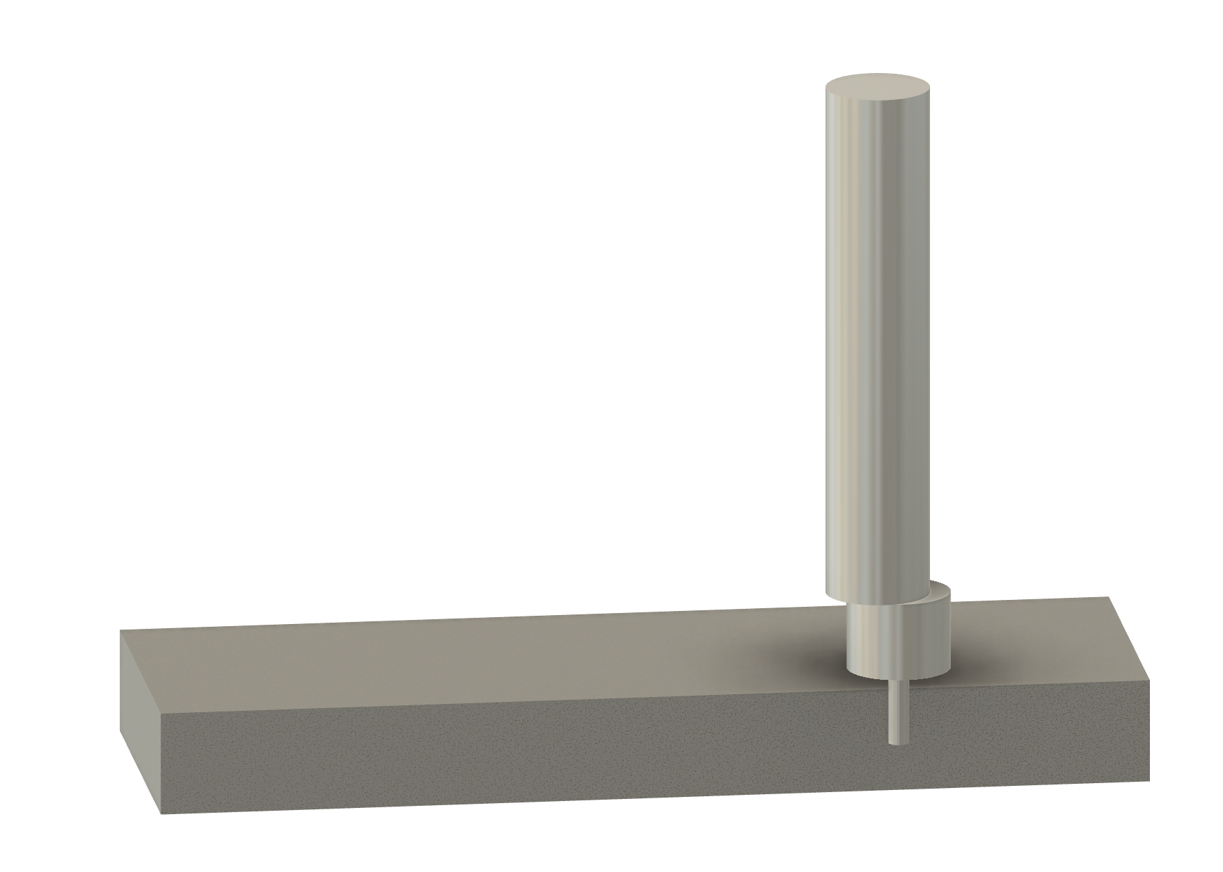
Spot and drill again at this location. Use a drill just a few thou smaller than your reamer size. Since I used a 0.376” reamer, I drilled with a letter U drill (0.368” diameter).
Be sure to create a generous chamfer at the top of the hole for the puck. Otherwise the puck won’t seat well because of the fillet at the base of the boss (from the lathe tool nose radius when we make the puck).
Finally, ream the hole with the reamer. Use plenty of cutting fluid and slow down the spindle speed to about 1/3 of the normal cutting speed for that size drill.
It’s best to ream the hole for the puck 0.0005” to 0.001” larger than the turned diameter of the boss on your pucks. If you don’t have a set of under/over reamers for nominal dimensions, be sure to turn the diameter of your puck bosses about 0.001” less than the size of whatever reamer you have available.
Honestly, a good sharp 3/8” drill probably suffices without reaming. Typically, though, drills cut slightly oversized and not entirely round holes.
Whatever size hole you end up with, you can always adjust the size of the boss on the puck with the lathe until it just fits without any slop.
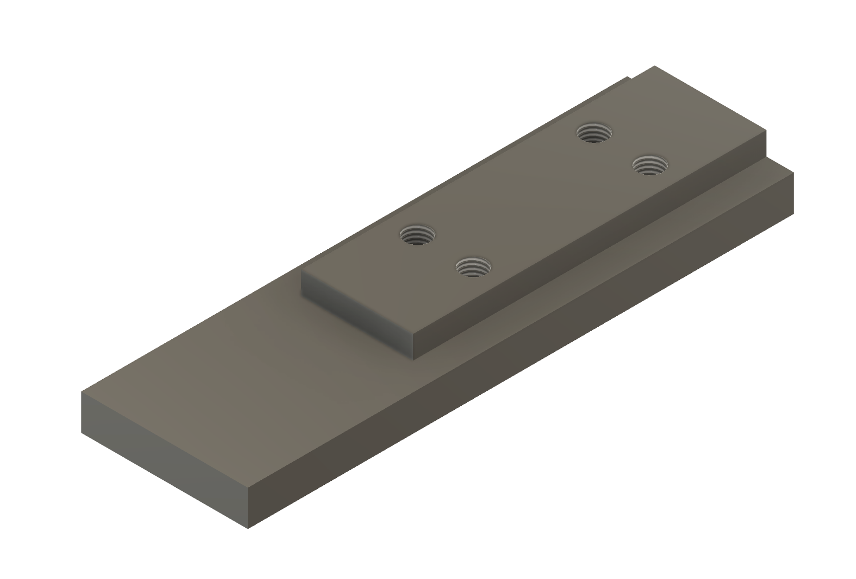
Conclusion
At this point, the tee slot base is complete. You can remove the part from the vise, deburr all the edges (all corners and especially the holes on the bottom where the drill broke through).
You should end up with a tee base that slides easily in your compound and looks something very similar to the top part here:
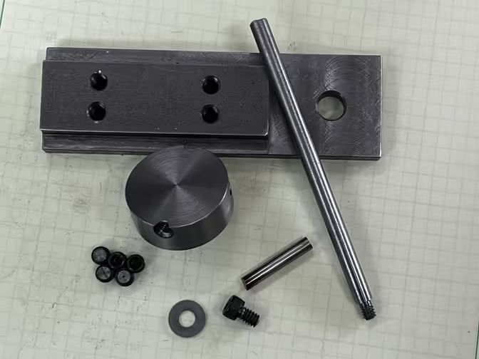
Note that unlike a normal toolpost, the screws don’t compress the “ledge” of the compound. This base is not a tee nut. The screws force the top of the base into the ledge of the compound.
In theory, this means that if you really gorilla the screws, you could damage the ledge on your compound. Don’t do that. There is absolutely no need to really gronk down on this base in the compound. All the cutting forces are purely tangential, toward the floor.
If this aspect of the design bothers you, you can make the base a nut and make another clamp part with through holes for bolts that goes on top (just ensure that the height of the base is less than the height of the slot and that the swivel handle clears the clamping parts).
The tee slot on your compound is intended to handle fairly significant forces (say from an extended boring bar) though – personally, I feel this is a theoretical rather than a practical concern.