Ball Turner Build: 2
Making the swivel puck: lathe work
This is a companion article to the original post detailing the construction process.
- Introducing Jim’s ball turner
- The build, part 1: tee slot base.
- The build, part 2: swivel puck assembly: lathe work [this post]
3D model and CAD drawings
As I wrote previously, I’ve made a 3D model available for viewing and download as well as a set of dimensioned drawings for my lathe.
For anyone using modeling software other than Fusion360, here are the step files for the design.
The dimensions are for my lathe specifically, but the model is fully parametric (if you use Fusion360). You can just enter the dimensions for your lathe, etc., and the model should update automatically (Modify -> Change Parameters). Just let me know if I’ve screwed something up.
My blog very intentionally doesn’t support comments or questions, but if you’d like to discuss this further, please see this thread on the Hobby Machinist forum.
Tools I used
- lathe
- left-hand turning tool (I also use it for facing). I think all hobbyists should learn to hand grind HSS tools, but insert tooling also works.
- set of gauge pins from 0.061” to 0.500” (minus) diameter
- 1” micrometer
- small pair of digital calipers
- 3-jaw self-centering chuck
- 3/8” collet that fits in my lathe spindle (I have to use 3C collets with an adapter)
- Jacobs chuck and adapter to fit into tailstock
- 142 degree spotting drill
- #25 drill (tap drill size for 10-24 screws)
- 10-24 plug tap
- 10-24 bottoming tap (for cutting the last few threads at the bottom of the hole)
- Chamfering/deburring tool to deburr hole prior to tapping
- spring loaded tap guide/follower
- tap wrench
Making puck blanks
I originally thought I’d make two holes in the top of each puck: one for cutting convex radii (balls) and another for concavities at the same radius. Because the cutter has a non-zero width, keeping the radius the same requires two different locations for the cutter.
After playing with a prototype, though, I’ve decided to stick with just one hole and one cutter (at a fixed radius) per puck. There are several reasons for this:
The KISS principle always applies. It’s hard to get simpler than a cylindrical cutter with one angle to grind (dead flat), that’s mounted straight up and down … at a fixed distance from a pivot point.
For cutting balls, the cutter needs to be behind the axis of rotation. This means you can’t leave a cutter in any other other hole, or it will interfere with the work. An empty hole is just a place for swarf to collect.
While adjusting a cutter to center height isn’t all that difficult, it’s mighty convenient if each puck already has a dedicated cutter pre-positioned on center.
Since I’m still making holes for the handle on both sides, you can still cut concavities just by relocating the handle. The concave radius will be larger than the convex one (by the diameter of the cutter), but if you have multiple pucks, this may not be that big a concern (and you can always make another puck or drill another hole if it is).
If, like me, you aren’t entirely sure what radii you might need, I recommend making pucks for at least a couple nominal sizes (3/4” and 1/2” balls, say) and also make a blank or two without a holes for the cutter and setscrew (just the handle).
Start by turning the puck blanks. Specifically, start by turning the boss on the bottom (you want to turn it to be slightly longer than the thickness of the “platform” on the base — more on this later).
In general, I prefer using collets whenever possible. Unfortunately, my lathe has a pretty small spindle, so I can’t use collets for larger diameter stock. So I chucked up a piece of stock as large as the puck diameter in a three-jaw chuck, then turned down the boss at the end.
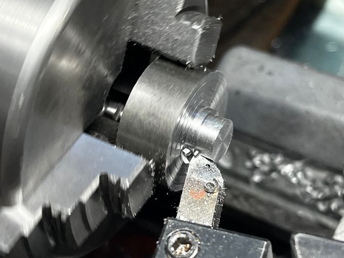
(If anyone wonders why I like turning “leadloy” aka 12L14 so much, just look at those chips!)
Note the “steps” in the face from turning to a stop after feeding ~0.100” each time during the roughing passes. These are due to the cutting face on the lathe tool being angled back slightly so that the nose contacts the work first.
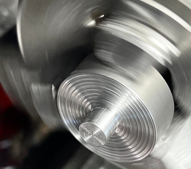
Once the boss is at final diameter, I make a final facing cut a few thou deeper to remove all the steps and leave a perfectly smooth face.
Since we want this to be a fairly precise fit into the bore we cut earlier, I stop using calipers when I get close to the final diameter and measure things accurately with gauge pins and a trusted micrometer.
Just because my cheap, offshore reamer is labeled 0.3760” doesn’t mean it actually cuts a hole that size. So I first start stuffing larger and larger gauge pins into the hole until they no longer fit. The last one that fits with a good feel tells me the diameter of the boss that I want to turn.
When the micrometer says you’re within a tenth or two, test the fit. Do NOT unchuck the part, of course, just move the base you already made to the work as it’s own gauge.
If you’ve read this far, you’ve probably figured out that I prefer to avoid measurements whenever possible, and rely on actual parts, gauges, and fixed stops whenever possible. Much less chance of error!
(Apologies if all the minutia seems overwhelming, but these are all things I’ve picked up over time and I think they are worth sharing with other beginners.)
Whenever I want to turn a feature with a fixed length like this, I like using a carriage stop. Many years ago, I made a stop using this design:
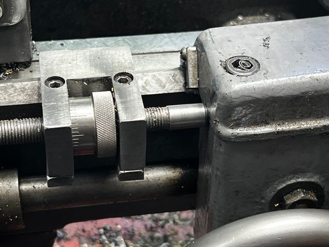
When I want to turn a feature to a pre-determined length, I first face the end of the stock, retract the cross-slide, then lock the carriage without touching the carriage handwheel.
Then I insert a gauge pin with a diameter equal to the desired measurement between the stop and the carriage (or a gauge pin in combination with a 123 block for longer dimensions):
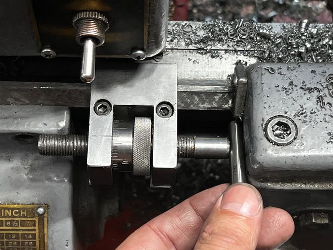
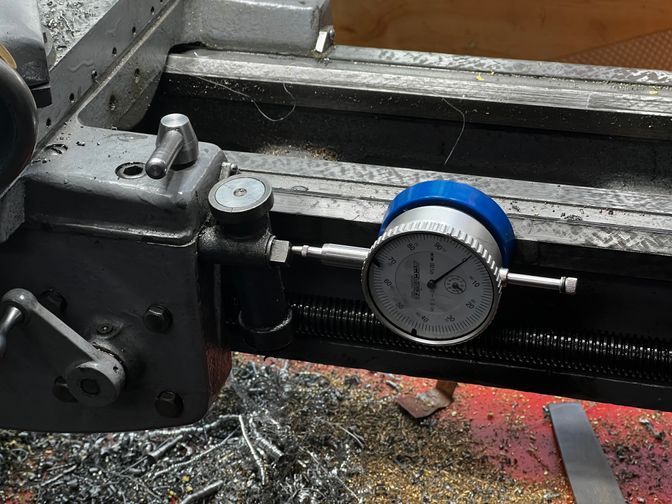
If you don’t have a stop (or a DRO on your lathe) I strongly recommend making one (Tom’s design is a good one). Alternately, though, a magnetic back on a dial indicator makes for a good “poor man’s DRO”:
In this case, I only needed to grab the correct pin (0.304” diameter) from the box. No measuring, no indicating, no fuss.
I do trust my ability to read a micrometer accurately (within a tenth or two) and dials within about a half thou, but I still check the fit with the actual part.
On the final pass after turning the boss to the correct diameter, I retract the micrometer stop by a few thou (a few divisions), move the carriage to the left that much, then face off the shoulder. This removes the steps described earlier.
Note that the boss should still be a bit proud of the bottom of the tee slot base at this point.
Completing the boss
Before removing anything from a chuck, it’s always a very good idea to stop and think about any other work you might be able to do in the same setup. Once you remove a part from a chuck, you’ll never get it back exactly the same way again without carefully indicating in the face and side in a four-jaw chuck.
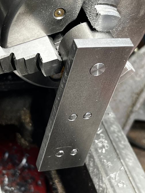
In this case, we obviously still need to drill and tap the hole for the retaining screw and washer.
The hole for the screw is a blind hole with a fixed depth. If you have a compound mounted Jacobs chuck, you can use the same gauge pin trick to drill to depth. Using the tailstock, you’re reduced to reading the graduations on the quill (or a converted pair of calipers mounted to the tailstock).
Once that work’s complete, we should adjust the length of the boss. The process below makes for a very precise feel when the retaining washer is clamped down.
Ideally, we want the length of the boss to be no more than a tenth or three proud of the bottom of the base. This will prevent the puck from wiggling at all when the screw is fully tightened, while still allowing the puck to rotate freely.
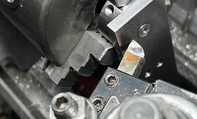
To accomplish this, first hang the base off of the boss, registering on the just faced shoulder as shown above. Then bring the nose of the cutter lightly in contact with the bottom of the base. Leave the power OFF for this step, of course!
Now, before turning on the lathe, retract the cross-slide and remove the base. Then face the boss to length without moving the carriage.
Turn off the lathe again, and try the fit. Insert the retaining screw and washer and tightening it fully to gauge the fit. There should be no detectable wobble at all as you lightly push, pull, and twist the base, but it should still spin freely.
If there is still a bit of wobble, remove the base and face off the tiniest bit of metal again, no more than 0.0005” at a time (easier if you feed with using the compound dial with the compound at an angle). Repeat until the fit feels perfect.
It’s best if you get it spot on, of course, but it’s not the end of the world if you go too far (it just means you can’t tighten the screw fully or you’ll prevent the puck from spinning).
One more piece of minutia: stamped washers leave a sharp burr on one side. Either ensure this side faces away from the bottom of the tee base, or rub the washer on a piece of emory backed by something hard and flat until the burr disappears (or both).
Turning and facing the remainder of the puck blank
Now you can finally remove the puck from the chuck.
Turn it around and hold the boss in a collet, then face the top side of the puck (continue until the puck is the desired thickness).
Unlike chucks, you can remove the part from a collet as many times as you want without losing concentricity. It is possible for a small amount of runout on the face to be introduced if you remove and reinsert the part, though, so it’s good practice to indicate in the face after reinserting, tapping the proud edge lightly until it runs perfectly true.
Once the top part of the puck is the desired thickness, turn the outside of the puck to ensure it’s concentric with the boss. This isn’t strictly necessary, but it looks better and eliminates a potential source of error if you use the periphery to locate the center (axis of rotation) in future machining steps.
Next: Making the puck (mill work) [COMING SOON)