Ball Turner Build: 3
Making the swivel puck: mill work
This is a companion article to the original post detailing the construction process.
- Introducing Jim’s ball turner
- The build, part 1: tee slot base.
- The build, part 2: swivel puck assembly: lathe work
- The build, part 3: swivel puck assembly: mill work [this post]
3D model and CAD drawings
As I wrote previously, I’ve made a 3D model available for viewing and download as well as a set of dimensioned drawings for my lathe.
For anyone using modeling software other than Fusion360, here are the step files for the design.
The dimensions are for my lathe specifically, but the model is fully parametric (if you use Fusion360). You can just enter the dimensions for your lathe, etc., and the model should update automatically (Modify -> Change Parameters). Just let me know if I’ve screwed something up.
My blog very intentionally doesn’t support comments or questions, but if you’d like to discuss this further, please see this thread on the Hobby Machinist forum.
Tools I used
- Vertical mill
- mill vise
- vise mounted stop
- table mounted stop
- Jacobs chuck for drilling (with R8 spindle adapter)
- 5C square collet block
- 3/8” 5C collet
- gauge pin set to 0.500” (to set stops)
- edge finder
- tap follower
- tap wrench
- 142 degree spotting drill(s)
- #25 drill (tap drill for 10-24). Up to #20 or 5/32” drill also okay
- #3 drill (tap drill for 1/4-28). 7/32” or 5.5mm also okay
- 10-24 plug and bottoming taps
- 1/4-28 plug and bottoming taps
- 11/64” drill (slightly undersized for 3/16” cutter hole)
- 0.1890” chucking reamer (~0.001” oversized for 3/16” cutter)
- 1/4” end mill (to counterbore the hole for the handle)
- 6” bench grinder or belt sander (to grind the end of the cutter)
- 10-24 die (to form the threads at the end of the handle)
Spot, drill, and tap for set screw
Begin by boring and tapping the hole for the set screw in the side of the puck. You want to drill and tap the set screw hole first, and drill and ream the hole for the cutter last, to ensure a clean bore for the cutter.
I used a square collet block to hold the work. Just hold onto the 3/8” boss, then tip the block onto it’s side in the vise as shown.
I tend to automatically set a stop whenever I use a collet block, so that I can remove and re-insert the work (or complete multiple parts) without losing location. In this case I was making multiple pucks, and I wanted to retain my DRO settings and part location whenever I changed parts.
Note that it’s almost always better to register a stop against a reference feature on the part itself, rather than to register against a fixture (the collet block or whatever). While it’s possible to register the stop against the collet block here, there’s no guarantee that you will re-insert a puck to the same depth each time. If you register against the top of the puck, it doesn’t matter. Always check and think through what you use as a reference!
For the first part, locate the top of the puck with the edge finder. My edge finder tip diameter is 0.200”, so after the edge finder jumps, I zero X on the DRO, move over another 0.100”, and re-zero again. Then I move to where I want the hole from the top (I put it 1/3 of the distance from the top to the bottom of the puck).
Then spot for the hole.
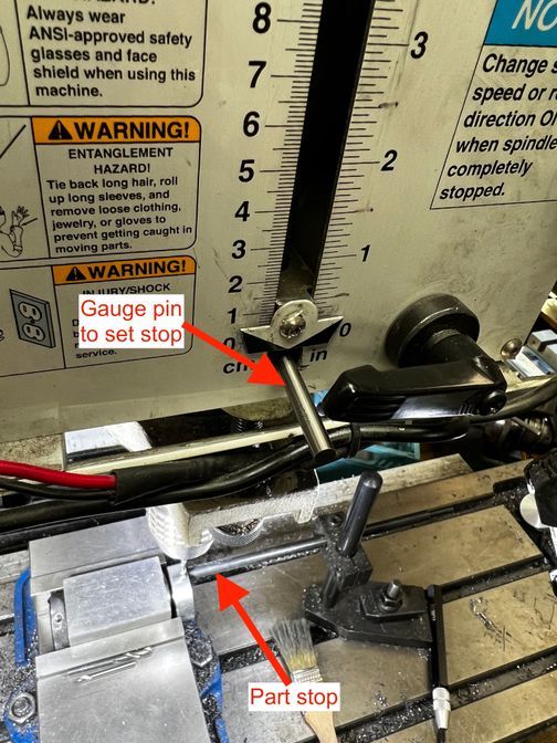
Next, drill to the appropriate depth with the #3 drill. Note That I use the quill stop with gauge pins to drill to a fixed depth.
With power off, lower the quill until the tip of the drill touches and lock the quill.
Then insert a gauge pin with the same diameter as the desired depth between the quill stop and the adjustable nut. Adjust the nut until it just pinches the pin. Now, if you remove the pin and lower the quill, you will hit the stop once you’ve reached the desired depth.
Once the hole is bored, put a tap follower in the drill chuck, and tap 1/4-28 with the plug tap until it bottoms out. The switch to a bottom tap and repeat (to cut threads all the way to the bottom).
Repeat these steps to drill and tap set screw holes in all the pucks.
Drill and ream the hole for the cutter
Now spot, drill and ream a hole for the cutter.
First stand up the collet block vertically, using a small square registered against the bottom of the vise to ensure it’s vertical. Again, set a stop to retain your location between parts. I used a vise mounted stop registering against the collet block this time, but since the collet registers on the diameter of the boss, it’s okay not to register against a feature on the part itself.
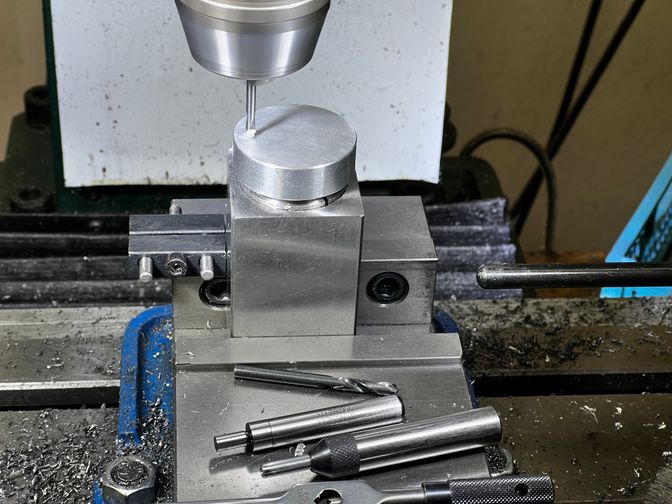
For the first puck, use the edge finder in X, then again in Y to find the exact center of the part.
Verify that the puck is rotated so that the set screw hole is below where you are about to drill!
Now use the DRO to position the spindle the desired radius distance from the center. Then spot and drill with a 11/64” drill to a depth of 1/2” (using a pin again).
Finally, ream the hole to be 0.001” oversized for a tight but slip fit for the cutter.
Repeat for the remaining pucks.
Handle holes
Next we will counterbore, spot, drill, and tap the angled holes to attach the handle. We will do this at two locations for each puck (180° apart from each other) to allow us to use the same tool for both inside and outside radiusing.
First, draw a radial line approximately where you want the handle to be positioned (the drawing suggests about 75° from the set screw hole which is a reasonable starting point, but it’s a matter of preference). Note the cap screw to make it easier to judge the line of the set screw hole.
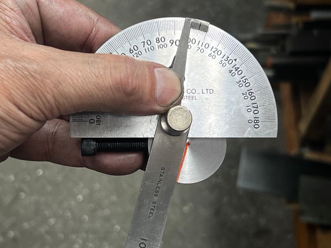
Now rotate the part in the collet so that the marked line points upward when the collet block is in the vise. Tilt the block the desired angle in the vise and clamp the collet block tightly. (The drawings suggest 30°, but this is also a matter of preference — you just need to ensure you clear the cap screws in the tee slot base.)
I used a 1/4” end mill to make the counterbore. It’s bad practice to hold an end mill in a Jacobs chuck, but in this case, this is just a plunge cut with no side loads, so I didn’t bother to change to a collet or end mill holder.
After creating the counterbore, spot then drill with a #25 drill. Then tap by hand, first with a plug tap, then a bottoming tap.
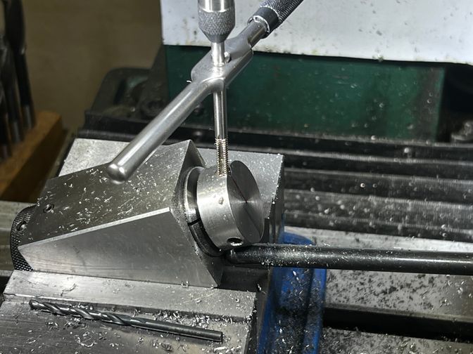
Again, with blind holes, it’s best to tap by hand rather than risk power tapping.
Now remove the collet block, flip it over, and repeat the counterbore/spot/drill/tap process for the other hole.
Then repeat for the remaining pucks.
Note that I’ve again set a stop, but with the stop against an angled face (I kind of nestled it between the part and the collet for two points of contact) it isn’t really a precision locator. You may need to jostle the X position slightly each time, but this is just for cosmetics.
The pucks are now completely machined!
Making the handles
The handles are easiest to make on the lathe. I just used 1/4” mild steel rods about 4” long. Single point or use a die to thread 10-24 on one end.
The other end can be left plain, or you can add a ball end if you desire!
For the ball, you can either use thicker stock and turn away the unused material (wasteful) or use 1/4” bar stock with a piece of 1/2” or larger stock attached to the end. You can thread the end of the rod to attach the thicker piece, or simply braze or glue on the thicker material. Then use your new ball turner to make the ball end.
Take care not to get two aggressive forming the ball, though, if you use CA glue. Turning a ball removes a fair bit of material and can warm up the ball enough to melt the glue (ask me how I know).
Making the cutters
The cutters couldn’t be simpler. They are just pieces of ground and polished high speed steel or carbide. Broken or worn out end mills make great cutters, but 3/16” HSS round lathe tool blanks also make a cheap source of cutters.
Just cut them to rough length, then grind the top perfectly flat. This is easily done by hand with a 6” bench grinder wheel, or a belt grinder. Just ensure that the top edge of the cutter is dead sharp all the way around.
Technically, a 6” grinding wheel will cut a slight hollow in the top of the part. For 3/16” or smaller cutter diameters, however, this hollow will be imperceptibly small and can be ignored. For larger cutter diameters, you might want to position the highest point with the outer periphery of the puck.
The easiest way to position the cutter on center is as follows:
Chuck up any piece of scrap in the lathe. Face the part with a sharp tool, but leave the smallest “pip” you can on the face of the part (lower the cutter a tiny amount off of center height, or just don’t face all the way across).
Now install the ball turner on your compound, loosely tighten the cutter set screw, then adjust the height of the cutter height until it is no higher than the exact center of the pip. Fully tighten the set screw.
Attach the handle, and your tool is complete. Go make some balls!
Conclusion
That concludes this build series.
I really hope many people make this tool. It’s a great beginner project and a truly useful tool. I had a lot of fun making mine.
Please let us know on the hobby machinist thread if you do end up making one of these!