Jim S. Ball Turner
A simple tangential cutter ball turner design
- Introducing Jim’s ball turner [this post]
- The build, part 1: tee slot base
- The build, part 2: swivel puck assembly: lathe work
I’ve been meaning to make a ball turner forever, and every time I’ve seen the topic come up on hobby machinist or any of the various mailing lists I’m on, my friend Jim S. inevitably pipes up with his design that he swears is the simplest possible. Yet everyone always seems to end up making something much more complicated!
About the designer
Jim is an old pro and has done some amazing work. For fun he’s turned a 3/8” solid sphere inside a 5/8” sphere, inside a 7/8” sphere, inside a 1” cube. Each hole is 1/16” smaller than the object it contains. All of the captive parts are free to rattle around inside the next larger part.
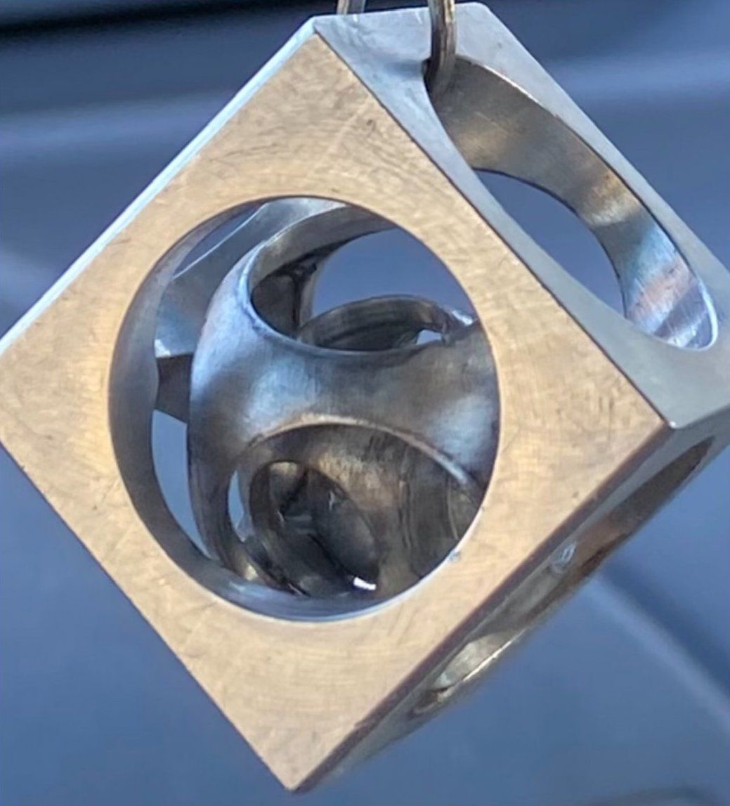
Try to figure out how to turn that!
He’s also made a rod with a doughnut shaped ring, but captured on the rod by turned balls that are larger than the ID of the ring. He’s even done two rings.
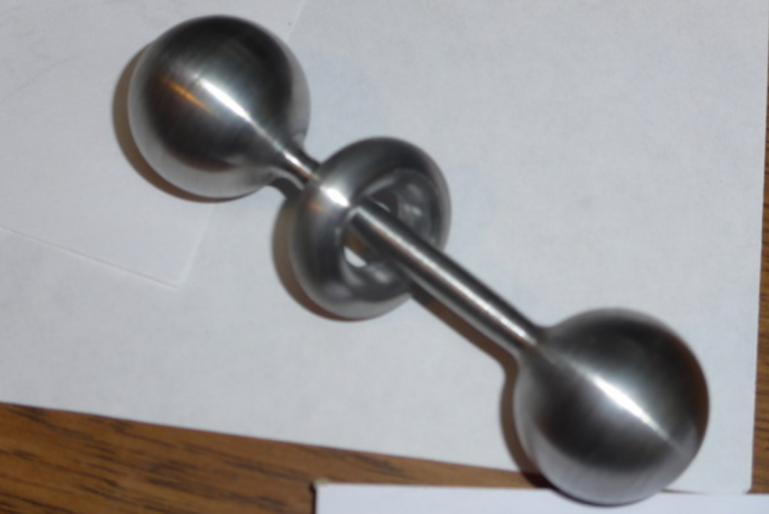
He used his ball turner idea (and other home built tools) to make at least the latter, as well as all sorts of other parts.
Anyway, I finally got around to making one of his ball turners for myself, and I see why he’s so enamored of the design. It works fantastically well!
Ball turner 3D model, drawings, and discussion
I’ve made a 3D model available for viewing and download as well as a set of dimensioned drawings for my lathe.
For anyone using modeling software other than Fusion360, here are the step files for the design.
The dimensions are for my lathe specifically, but the model is fully parametric (if you use Fusion360). You can just enter the dimensions for your lathe, etc., and the model should update automatically (Modify -> Change Parameters). Just let me know if I’ve screwed something up.
My blog very intentionally doesn’t support comments or questions, but if you’d like to discuss this further, please see this thread on the Hobby Machinist forum.
Safety warning
I can’t be held responsible if you somehow manage to hurt yourself making one of these things. Machine tools can be dangerous if you don’t know how to use them safely. Heck, any tool can be dangerous.
Learn how to use your machines safely elsewhere before attempting to make one of these. I’ve tried to only present tried and tested techniques, and I’m unaware of any operations that are particularly dangerous, but your safety is your responsibility, not mine.
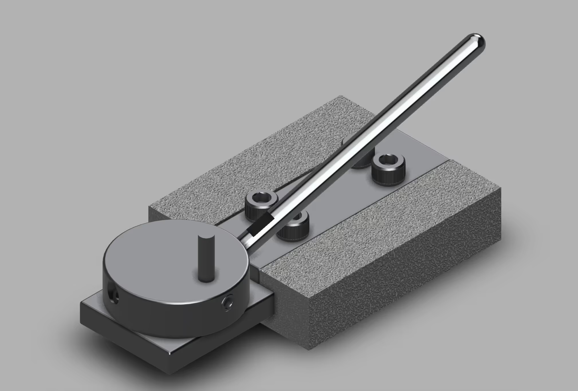
The design
The key characteristic of the design is that it uses a tangential cutter with zero rake and zero relief. Many people will swear up and down that such a tool won’t cut, but I’m here to tell you it works fantastically well.
No top rake is no big deal. It’s pretty common when cutting harder materials (Jim is pretty sure the design will work just fine with a carbide cutter even on super hard alloys like inconel).
The cutter is a precisely ground cylindrical rod with a flat face (the remains of an old end mill, center drill, or whatever work just fine). The curve at the edge of the top face means you initially have point contact, but you’ve effectively got a super large nose radius, which leads to an outstanding surface finish.
Zero relief is what breaks people’s brains. It seems like it wouldn’t cut at all, but for turning (vs. facing), rod-shaped cylindrical work already provides plenty of relief. With the cutter at center height, the work already curves away below the cutting edge — additional relief really doesn’t have any advantage (clearance is clearance, Clarence).
Best of all, it’s a tangential cutter: all the cutting forces are 100% in line with the long dimension. It could not be a more rigid setup. There is virtually no chance of chatter, and you can make surprisingly aggressive cuts without any problem.
About the only limitation of zero relieve is that you CANNOT face stock by feeding out, nor feed directly into a faced end of stock, you must feed into the side of the stock on every pass (keep the carriage locked and just feed in on the cross-slide).
Here’s an example of the tool in action:
Some notes about the video and the tool shown:
That is steel in case it isn’t obvious, not aluminum. Albeit leadloy (12L14) which is pretty forgiving to turn, but I’ve seen some pretty janky ball cutter designs that aren’t rigid enough to cut steel.
This was my very first attempt at using the tool. Out of an abundance of caution, I had the spindle speed extremely slow (like I was forming rather than cutting). It was simply much too slow!
I also was fumbling a bit, handholding my phone to record the action. Much of the jerkiness is because of these first two points. Still, I’m taking a reasonably aggressive cut. With your hands free, it’s extremely pleasant and actually fun to turn a ball. There isn’t even a hint of chatter or deflection.
It’s not obvious, but I could have continued swinging the handle left as far as I want to go (until the ball drops off the end). There is no need to cut the “neck” first, you can plunge the cutter right into the work.
This was an early attempt at Jim’s design, and on my little 10” lathe, I couldn’t cut any ball diameters larger than about 3/4”. I’ve since milled down the outboard portion of the platform, letting me cut balls up to just over 1” diameter with ease.
This is not an adjustable tool, it only cuts fixed radii. But it’s quite easy to make additional pucks with the cutter positioned for whatever radius you desire (up to the distance between the top of the puck and the top of the cutter).
Not shown (yet) is that the tool can also cut concave radii into the side of the stock. It’s not possible (without modification) to cut bowls into the end of a part, but that’s a less common need anyway. That is, in addition to cutting balls, you can also create quite accurate concave and convex fillets on cylindrical features. [Remember that you can only feed in on the cross slide and swivel the cutter outward, toward the tailstock. You cannot move the cutter left, toward the spindle — it will not cut.]
It’s convenient to set the swing radius to nominal stock sizes. That way, when the outer band of darker un-cut material just disappears, you’ll know the pivot is right under the center of a ball that’s now perfectly to size. For oddball sizes, first turn a cylinder of the correct diameter with a turning tool and mark the surface with dykem or a sharpie so you can track your progress.
About the cutter
The cutter can be any cylindrical piece of high speed steel or carbide. Old, broken, or worn out end mills, center drills, or whatever are perfect. The diameter of the cutter isn’t terribly important, but it probably makes sense to keep it between 1/8” diameter and 5/16” diameter. Too small, and you risk it snapping due to accidents. Too large, and you limit the maximum sized ball you can turn.
You can also buy pre-hardened HSS blanks, drill rod, or whatever, cut into the lengths you need. You just want something hard with a nice ground and polished surface on the OD. You then grind and polish the top surface perfectly flat (forming a sharp cutting edge all the way around).
The easiest way to cut hardened stuff to rough length is by scoring the OD with a cut-off wheel in a Dremel tool or angle grinder, then holding it vertically in a vise near the score. Cover the top with a rag to hold the part, then whack it with a hammer. It will snap right at the weakest point. Finally, grind the top perfectly flat and (optionally) polish on a stone.
You just need to hold the tool perpendicularly to a grinder to form the flat (belt sander, bench grinder, slow-speed grinder, whatever). You must continue grinding until you have a perfectly flat face and smooth circular edge all the way around (with no trace of the earlier scoring).
I used my Quorn T&C grinder to grind the face, but I’m sure it’s fine to just point it at the center of even a 6” bench grinder wheel and grind away on the periphery of the wheel. The slight hollow produced actually provides a bit of top rake! Just be sure to position the high part of the grind away from the center of the puck when you adjust the cutter height.
The cutter must be exactly at center height to cut a precise radius. For a convex ball, you drill and ream a hole about 0.001” larger in diameter than the cutter into the top of the puck. If the desired cutting radius is R and the cutter radius is c, you position the hole R + c away from the center of the puck for a convex radius (that cuts on the inside of the cutter, with the pivot point under the work) or R - c for concave radii with the pivot point between the operator and the work.
If the cutter is slightly below center it’s no big deal (the diameter of the sphere will just be a little off), but if it’s above center even a tiny bit, the tool will just rub and won’t cut.
There are many ways to position on center, but probably the easiest is to just put either a split-point single-lip cutter in a collet in the spindle, or just put a sharp center in the spindle.
You then adjust the cutter up and down until it touches the flat oriented horizontal in the spindle, or until it just meets the sharp point of the center (you can just cut a taper with a sharp point into a piece of scrap held in the chuck if you don’t have collets or a center). Then tighten down the set screw in the side.
If you really want to be precise, you can put a gauge pin in a collet and use a height gauge to mark center height. Position the height at the top of the pin. Say it’s a 1/2” gauge pin. Now lower the arm by exactly 0.250 and you’ve got a reference for center height. Adjust the cutter until it just touches the arm of the height gauge (you can also use a depth micrometer registering on top of the gauge pin).
Or do what I do, and zero an indicator at top dead center of a gauge pin in a collet in the spindle, then roll a pin on top of the cutter that’s half the diameter of the one in the spindle. Adjust the height of the cutter until the indicator reads zero again when you roll past TDC of the smaller pin.
Screws
I initially used set screws for the tee slot, but regular socket head cap screws work fine as long as they don’t interfere with the swivel handle.
You really want flat ends, though, not the common cup points on set screws. Cup points will mar up the bottom of your compound. They are unlikely to damage the much harder cutters, but it’s still a good idea to face off the cup points even for the cutter set screw.
The diameter and thread pitch of the screws really aren’t all that important. Use whatever you have on hand, but in general, fine thread pitches will let you lock things more securely. It’s a good idea to use UNF pitches (10-32, 1/4-28, etc.) for holding tasks.
Cutting a ball on the end of a rod
The thing couldn’t be simpler to use.
I prefer holding the work with collets rather than in a chuck for two reasons:
No fear of getting my knuckles close to the spinning jaws of death as I pivot the handle to the left.
Collets let you hold the work much closer to the end of the spindle, increasing rigidity.
You don’t even need to face the stock before beginning. Just position the compound with the handle directly toward the operator or a little to the left before installing the tee base of the cutter. You just want the slot running roughly left to right (and maybe a little forward).
Put some nominally sized stock into a collet, swing the handle to position the cutter toward the tailstock, feed in the cross-slide until the center of the puck is roughly under the bar, then move the carriage until the cutter just bumps the end of the stock (as shown below).
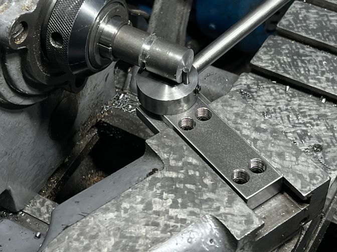
Now retract the cross-slide, move the carriage a smidge more to the left (enough to clean up the end of the stock), and then start swinging the handle left and right as you slowly start feeding in the cross-slide.
Because you ultimately turn off the entire end of the shaft, it suffices to position the carriage by eye initially.
Note that you can also plunge right into the side of the stock to form the “neck” behind the ball. You don’t need to pre-cut the neck (as I did unnecessarily in the photo).
Note that because the tool has such a wide “nose” radius and the depth of cut is controlled by feel, it’s pretty great at blending into another feature that you might have cut with other tools.
It can also create generous fillets at an inside shoulder.
Again, remember that you can’t face! Always feed into the OD of the stock and lock the carriage. Never move the carriage left into a face while using the ball turner.
Next: Building the tee base